Material thickness and the thickness of its coating are different questions. Even at the same 100 μm, paint on aluminum, a polymer coating on plastic and metal plating can need different methods. These guides explain which layer to measure, what to tell a supplier and how to check the resulting measurement.
Choose a method to read its full explanation below. This comparison is a starting point; confirm the actual material, geometry and range before selecting an instrument.
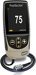
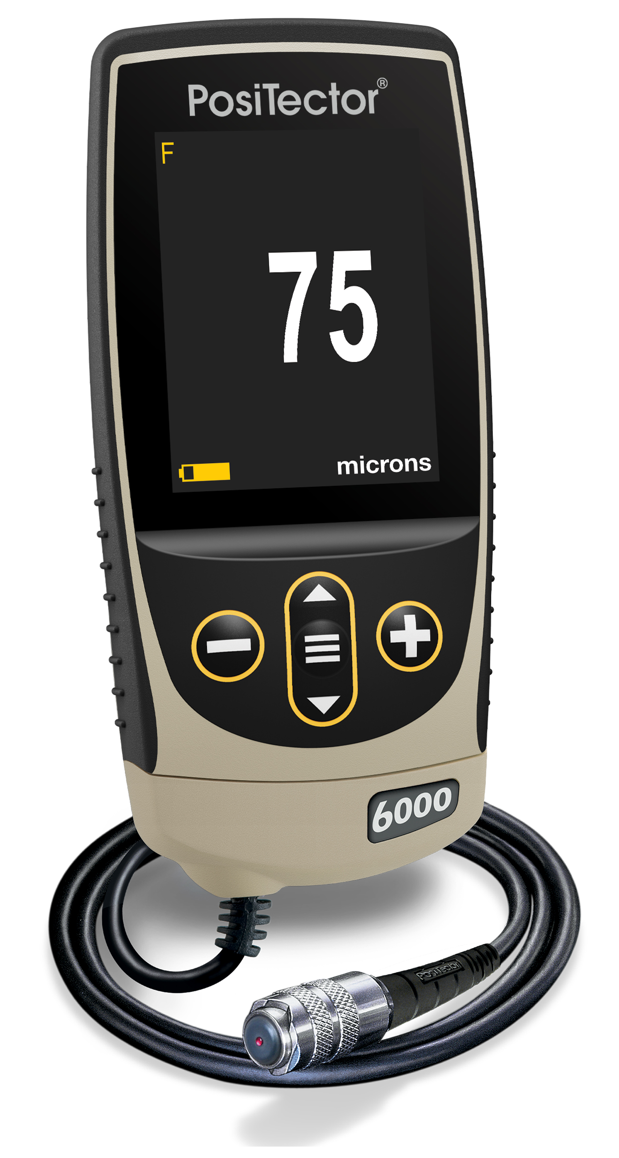
The sensor detects changes in a magnetic field as it reaches the steel substrate. The signal changes with the thickness of the nonmagnetic layer between the sensor and the steel, allowing that distance to be measured.
Suitable applications
Total thickness of paint, powder coatings and nonmagnetic zinc layers on iron or carbon steel.
Limitations
Not suitable for aluminum or nonmetal substrates. Standard measurements cannot resolve individual layers in a multilayer coating. The magnetic properties of nickel layers also need to be checked.
Before measuring
Check substrate magnetism, curvature, surface roughness and substrate thickness. Adjust the zero on an uncoated sample of the same substrate material.
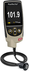
An alternating magnetic field induces eddy currents in the metal substrate. The sensor measures how the coating changes the response. Conventional amplitude-sensitive instruments measure insulating layers on nonmagnetic conductors.
Suitable applications
Anodizing and powder coatings on aluminum; insulating coatings on copper.
Limitations
A general-purpose eddy-current coating gauge cannot directly measure metal plating on metal. Phase-sensitive instruments for metal plating require a different configuration and application checks.
Before measuring
Check substrate conductivity and magnetism, distance from edges, curvature and the required measuring range.
The instrument measures the time it takes for sound to travel through a material and return from the back wall. With the material sound velocity and round-trip time, thickness can be measured from one side.
Suitable applications
Remaining metal pipe wall thickness, metal sheets and suitable plastics, glass and composites.
Limitations
Material, grain structure, porosity and surface condition affect the signal. Coated substrates require a compatible probe and a measurement mode that excludes the coating contribution.
Before measuring
Check the actual material sound velocity, probe and frequency, couplant, minimum thickness and surface temperature.
The instrument analyzes ultrasonic reflections from the coating surface and layer boundaries. Individual layers can be measured when their echoes are sufficiently distinct.
Suitable applications
Polymer coatings on wood and plastic; protective coatings on concrete and FRP.
Limitations
Not every multilayer coating can be resolved. Each layer must have sufficient thickness and acoustic contrast. Very thin or soft layers require sample evaluation.
Before measuring
Check coating material, total and individual layer thicknesses, interfaces, couplant and the B/C/D probe configuration.
X-ray excitation causes each element in the sample to emit characteristic fluorescent X-rays. Element signals and a layer-structure model are used to determine metal layer thickness and composition.
Suitable applications
Zinc, nickel and gold plating; alloy plating; multilayer metal films whose elements can be distinguished.
Limitations
The thickness range depends on the elements and layer structure. Signals can saturate in thick layers, and boundaries between layers of the same element may be difficult to resolve.
Before measuring
Check layer order, elements and density, measurement area and spot size, reference standards and shielding configuration.
Element-specific X-ray intensity → thickness and composition
Reflections from the upper and lower film boundaries produce an interference spectrum. The signal is fitted to an optical model that includes refractive index and layer structure to calculate thickness.
Suitable applications
Oxide films on silicon, photoresist and transparent or translucent polymer films.
Limitations
Not a universal method for opaque or rough films. Refractive index, absorption and optical model settings affect the result.
Before measuring
Check transparency over the wavelength range, surface roughness, refractive index and absorption, layer order and measurement spot size.
Reflectance interference spectrum → film thickness
The sample is placed between two measuring faces and their separation is read. Consistent measuring force and suitable face geometry provide repeatability.
Suitable applications
Rigid sheets and parts accessible from both sides; films measured with an appropriate force.
Limitations
Cannot isolate a coating from its substrate. Paper, soft films and rubber compress under measuring force and may require a dedicated low-force gauge.
Before measuring
Check measuring force, measuring-face size, parallelism, sample deformation and access to both sides.
An electrolyte dissolves metal plating over a defined area. Thickness is calculated from the charge required to remove the layer and the material properties.
Suitable applications
Single-layer and multilayer metal plating analysis; electrochemical layer evaluation.
Limitations
A destructive method that removes plating at the measurement point. Check the electrolyte, coating/substrate combination, current efficiency and endpoint detection.
Before measuring
Confirm that localized damage is allowed. Check electrolyte, cell area, metal type and layer order.
A cut at a known angle creates an inclined coating cross-section. Layer width is read through a microscope and converted to thickness using the cutter-angle factor.
Suitable applications
Paint on metal and nonmetal substrates; distinguishable single-layer and multilayer coatings.
Limitations
Leaves a cut in the sample. Cut quality can introduce errors in soft or brittle coatings.
Before measuring
Confirm that cutting is allowed. Check cutter angle, color contrast between layers and scale resolution.