PRACTICAL MEASUREMENT
Coated pipe: measuring the remaining wall
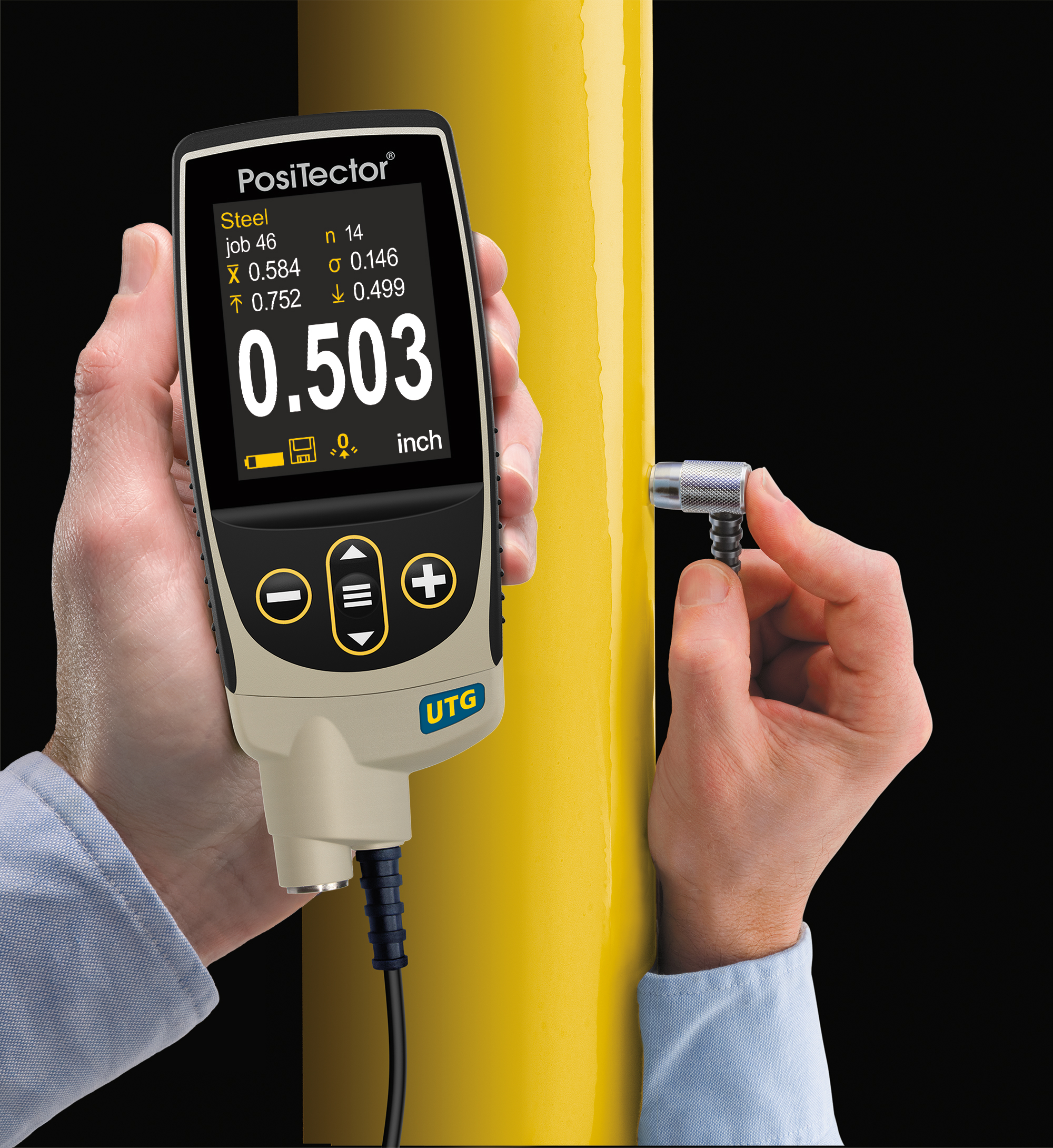
For a painted pipe, remaining wall thickness means the load-bearing material under the paint. A coating thickness reading does not answer that question. Ultrasonic measurement can provide access from one side, but the material, probe and echo interpretation must match the task.
Understand the travel-time calculation
In a simple pulse-echo measurement, d = v × Δt / 2. Here d is material thickness, v is sound velocity in that material and Δt is the round-trip time. The division by two accounts for the outward and return paths.
A velocity setting that suits one material is not automatically valid for another. The instrument needs a representative reference rather than a material name alone.
Reference: Evident — Ultrasonic Thickness Gauge Tutorial ↗Check velocity and zero with a reference
Use an appropriate reference of known thickness and follow the procedure for the selected probe. Velocity and zero adjustment address different contributions to the time measurement. References should represent the material and the thickness interval being examined.
Record which reference was used, its known thickness and the resulting check readings. Repeat the check when changing the probe, measurement setup or conditions in a way that could affect the result.
Reference: Evident — Velocity and Zero Calibration ↗Decide how the coating is handled
In a conventional measurement through paint, the coating transit time can affect the indicated wall thickness. Compatible multiple-echo or coating-exclusion modes can help separate that contribution, but they require a suitable probe and usable echoes.
Do not simply subtract a coating reading in micrometers from an ultrasonic wall reading. The sound velocities differ, so the apparent added thickness need not equal the physical paint thickness.
Reference: Evident — 39DL PLUS: corrosion and coating measurement modes ↗Ask for evidence at the difficult locations
Prepare a trial that includes the tightest curvature, roughest surface and thinnest expected wall, rather than only the easiest flat region. Ask the supplier to demonstrate whether the signal remains interpretable at those locations.
Create a location map for repeated inspection. Preserve questionable or missing readings as such; do not replace them with a neighboring value. A repeatable-looking display alone does not establish that the intended back-wall echo was selected.
- Brief the supplier on pipe material, diameter, expected wall interval and paint condition.
- Include actual surface temperature and whether couplant or coating removal is permitted.
- Ask for the exact probe and measurement mode used in the demonstration.
APPLICATION EXAMPLE
Worked calculation with an assumed velocity
For illustration only, let v = 5,900 m/s and Δt = 2.0 μs. The calculated thickness is 5.9 mm. The same time entered with a 10% higher velocity gives a 10% higher thickness. This example demonstrates sensitivity to the setting; 5,900 m/s is not a calibration value prescribed for every steel pipe.
A wall-thickness selection is complete only when the probe, reference, measurement mode and difficult sample locations have been checked together. Service acceptance limits must come from the responsible engineering specification.
References and editorial note
Technical explanations draw on the manufacturer references below. The planning steps and illustrative examples are thickness.biz guidance; they do not imply manufacturer review of this article or verification of a particular sample.